Before moving on, check out this image. It's a great resource for learning what each of the pins on your Atmega chip do in relation to the Arduino's functions. This will clarify a lot of confusion behind why you hook up certain pins the way you do.
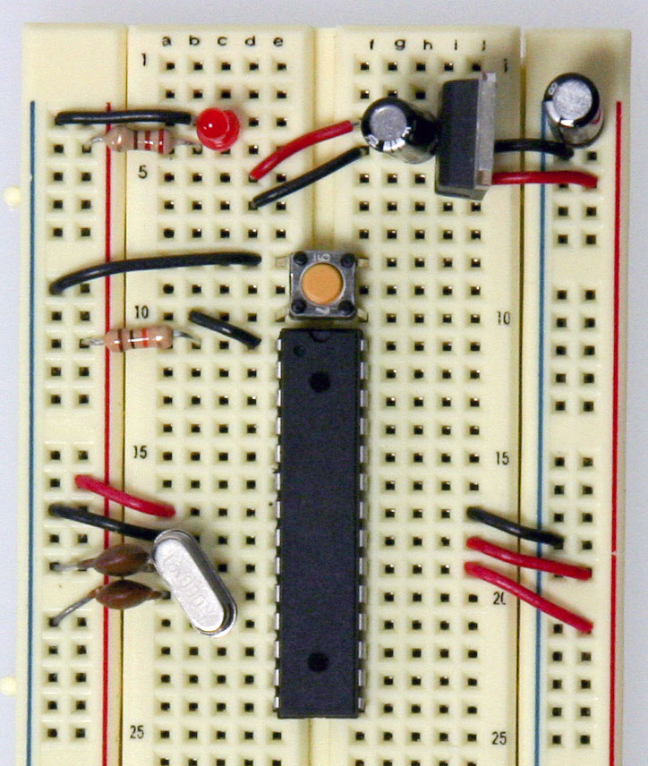
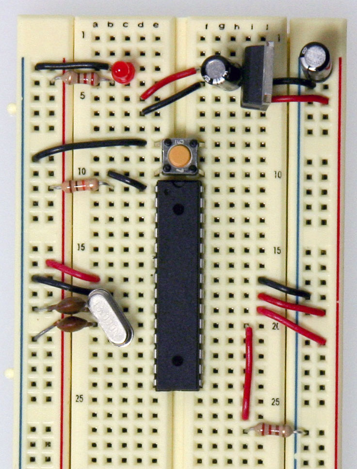
Start by connecting a 10k ohm pullup resistor to +5V from the RESET pin in order to prevent the chip from resetting itself during normal operation. The RESET pin reboots the chip when pulled down to ground. In later steps we will show you how to add a reset switch that takes advantage of this.
- Pin 7 - Vcc - Digital Supply Voltage
- Pin 8 - GND
- Pin 22 - GND
- Pin 21 - AREF - Analog reference pin for ADC
- Pin 20 - AVcc - Suppply voltage for the ADC converter. Needs to be connected to power if ADC isn't being used and to power via a low-pass filter
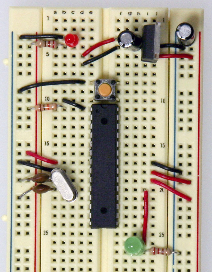
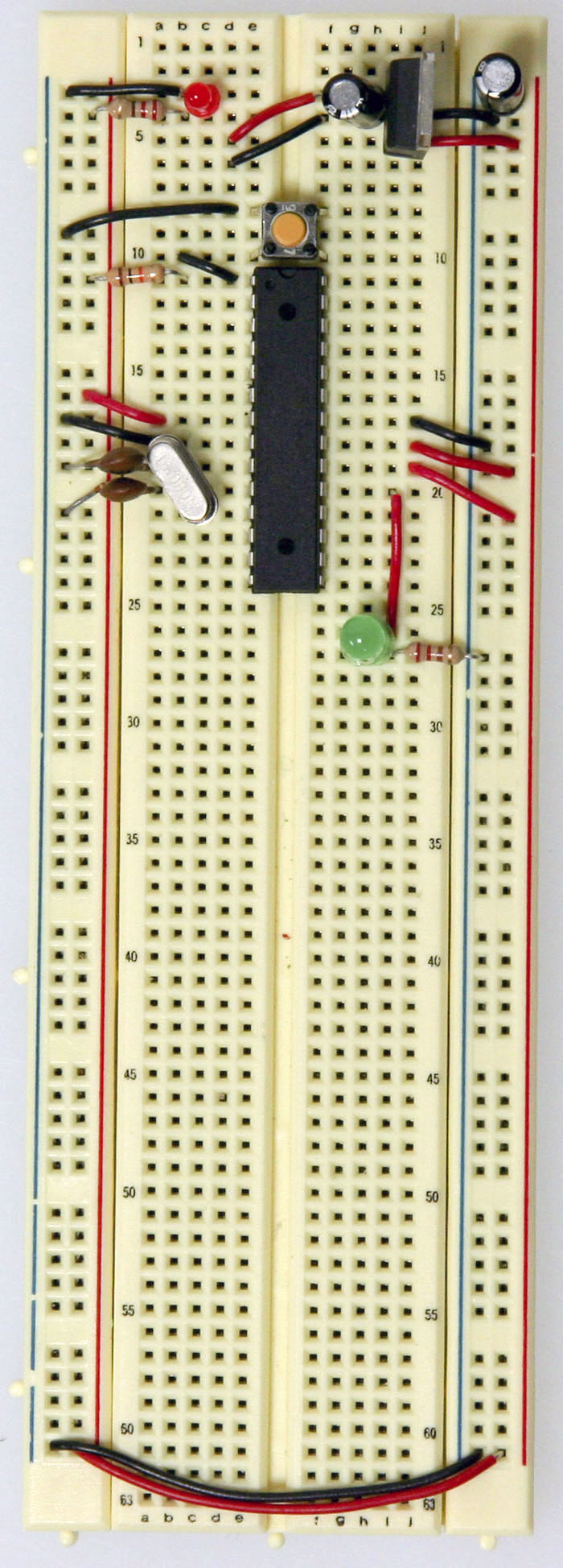
- Add a 16 MHz external clock between pin 9 and 10, and add two 22 pF capacitors running to ground from each of those pins.Add the small tactile switch so that you can reset the Arduino whenever we'd like and prepare the chip for uploading a new program. A quick momentary press of this switch will reset the chip when needed. Add the switch just above the top of the Atmega chip crossing the gap in the breadboard. Then, add a wire from the bottom left leg of the switch to the RESET pin of the Atmega chip and a wire from the top left leg of the switch to ground.The chip used on this board is actually already programmed using the blink_led program that comes with the Arduino software. If you already have an Arduino printed circuit board running, it is a good idea to go ahead and check the breadboard version you are building with a chip you know works. Pull the chip from your working Arduino and try it on this board. The blink_led program blinks pin 13. Pin 13 on the Arduino is NOT the AVR ATMEGA8-16PU/ATMEGA168-16PU pin 13. It is actually pin 19 on the Atmega chip.Finally, add the LED. The long leg or the anode connects to the red wire and the short leg or the cathode connects to the 220 ohm resistor going to ground.At this point if you had already programmed your chip somewhere else and didn't need this breadboard circuit to reprogram the chip, you could stop here. But part of the fun is in-circuit programming so keep going to really make a full USB-Arduino-circuit on a breadboard!


0 comments:
Post a Comment